Why the best PLC programmers don’t think about what turns things on. They think about what state the equipment should be in.
Most PLC programs start life as something straightforward. A motor with a start button and a stop button. A seal-in circuit or a set/reset. It works, it’s simple, and for a single motor on a test bench, there’s nothing wrong with it.
Then the project grows. Interlocks get added. A startup delay goes in. A fault condition needs acknowledging before the motor can restart. Someone adds a mode selector for automatic and manual. Then a maintenance bypass. Then a second motor that has to start before the first one. Before long you’re looking at a sequence where three motors start in order with delays between them, but only if a level transmitter reads above a setpoint and a valve has confirmed open within a timeout period.
At some point, without anyone making a conscious decision, the logic stops being a simple control circuit and becomes an implicit description of complex behaviour. Nobody designed it that way. It just accumulated. And now it’s a tangle of boolean flags, timers, and interlock chains that technically works but that nobody can confidently explain, modify, or troubleshoot.
This is the problem that state machines solve. Not by adding complexity, but by giving structure to the complexity that already exists.
Why Traditional PLC Logic Breaks Down
The fundamental issue with traditional PLC logic is not that it’s wrong. It’s that it describes mechanisms without describing behaviour. A network that energises a motor contactor based on a combination of permissive conditions tells you exactly what makes the motor run. What it doesn’t tell you is what the motor is supposed to be doing at any given moment, what it was doing before, or what it should do next.
In a small system, that doesn’t matter. You can hold the entire logic in your head. But as systems grow, several problems emerge that are almost universal across PLC projects.
Boolean flag accumulation is one that everyone has seen. Engineers add flags to track whether something has happened, whether a sequence step has completed, whether a fault has occurred, whether an acknowledgement has been received. Each flag makes sense in isolation. But after a few years of modifications, you end up with dozens of boolean tags whose interactions are nearly impossible to trace. The logic becomes a web of interdependencies where changing one flag’s behaviour can have unpredictable effects elsewhere.
Then there’s implicit sequencing. When a process needs to follow a series of steps, the sequence is often encoded as a chain of conditions rather than an explicit progression. Step 2 happens because the conditions created by Step 1 happen to be true, not because the program explicitly says “we are now in Step 2.” This works until someone needs to understand why the sequence stalled at a particular point, and they have to mentally reconstruct which combination of conditions represents which step. During a live plant issue at two in the morning, that’s not a fun exercise.
Scattered transition logic is the other one that catches people out. The conditions that move equipment from one mode of operation to another end up distributed across multiple networks, sometimes multiple blocks. Starting a pump might involve logic in the pump’s own block, the sequence block, the interlock block, and the HMI interface block. Understanding the complete picture of “what does it take to start this pump” requires reading code in four different places and mentally assembling the result.
None of these problems are caused by bad engineering. They’re caused by the absence of a structural pattern that makes behaviour explicit. That pattern is the state machine.
What a State Machine Actually Is
The concept is straightforward. A system exists in exactly one defined state at any given time. It can only move from one state to another through defined transitions. And the behaviour of the system is determined by which state it is currently in.
That’s it. No special hardware, no proprietary software, no complex mathematical framework. It’s a way of organising logic so that the behaviour of a piece of equipment or a process sequence is described explicitly rather than emerging implicitly from a collection of conditions.
Consider a simple centrifugal pump in a water treatment application. Without a state machine, the pump’s logic might consist of a start permissive chain, a run confirmation check, a fault detection network, and various interlock conditions. All of these interact with each other through shared boolean tags, and the “state” of the pump at any moment is whatever combination of those tags happens to be true.
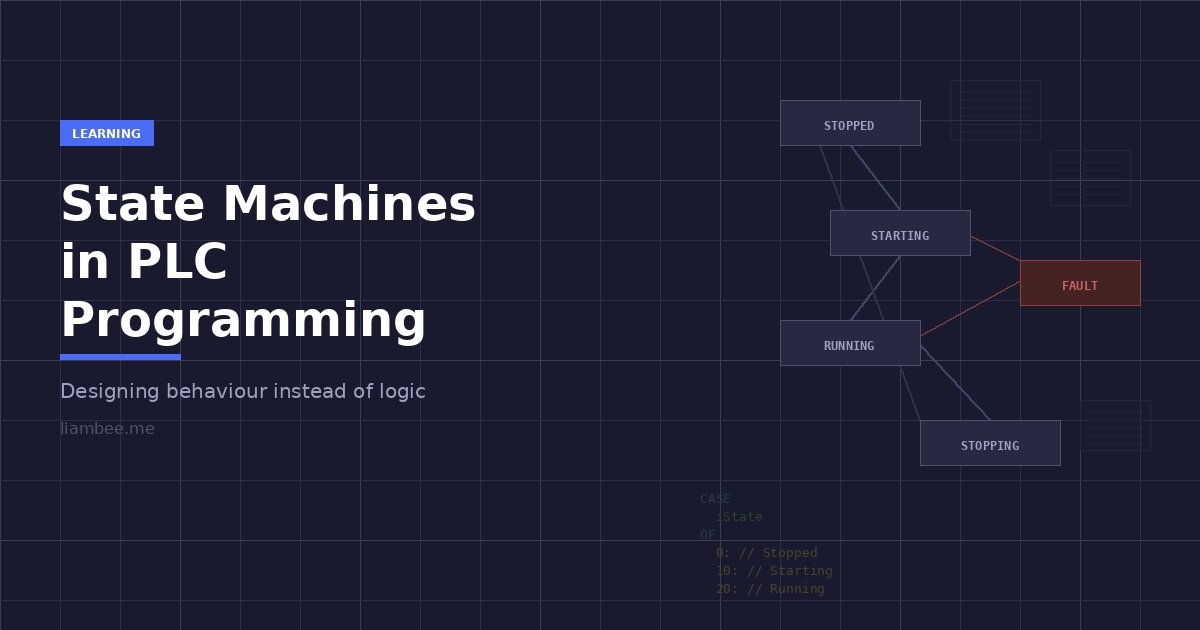
With a state machine, the pump has defined states: Stopped, Starting, Running, Stopping, and Faulted. At any moment, the pump is in exactly one of these states. The logic for each state is self-contained: when the pump is in the Starting state, it energises the contactor output and monitors for run confirmation within a timeout. When the pump is in the Running state, it monitors process conditions and responds to stop commands. When the pump is Faulted, it de-energises everything and waits for an acknowledgement before allowing a return to the Stopped state.
The transitions between states are equally explicit. The pump moves from Stopped to Starting when a start command is received and all permissives are healthy. It moves from Starting to Running when run confirmation is received. It moves from Starting to Faulted if the confirmation timeout expires. Every possible path is defined, visible, and traceable.
The mental model shift is this: instead of asking “what combination of conditions makes this output turn on?”, you ask “what state should this equipment be in, and what does it do in that state?” This changes how you design logic, how you debug it, how you document it, and how you explain it to operators and maintenance engineers.
Why PLC Scan-Based Execution Suits State Machines Perfectly
I sometimes hear engineers describe state machines as a software engineering concept that’s been awkwardly imported into the PLC world. It’s a fair concern, but in practice the opposite is true. The PLC scan cycle is almost perfectly suited to state-based execution.
A PLC executes its program cyclically. Every scan, it reads inputs, evaluates logic, and writes outputs. That is fundamentally a deterministic evaluation of current conditions, which is exactly what a state machine needs. Each scan, the PLC checks: what state am I in? Are any transition conditions met? If so, move to the new state. Then execute the behaviour associated with the current state.
This maps directly onto the scan cycle without any special constructs. No interrupts, no callbacks, no event handlers, none of the mechanisms that make state machines more complex in general-purpose software. The scan cycle is the evaluation loop. The PLC’s retentive memory naturally maintains the current state between scans. The deterministic execution ensures that transitions are evaluated consistently and predictably.
The implementation is equally natural. A single integer variable holds the current state. A CASE statement (or its equivalent in ladder logic using comparison contacts) evaluates which state is active and executes only that block of code. Open the block, see the CASE structure, and you know exactly which state the equipment is in and what it’s doing.
Compare that with the traditional approach where you have to mentally evaluate a dozen interlock conditions to figure out what the equipment is currently doing. The state machine makes the answer trivially obvious: read the state variable.
Real Industrial State Machine Patterns
The pump example above is the simplest case, a linear state machine where equipment progresses through a predictable sequence. But industrial applications use several different state machine patterns, and recognising which pattern fits your application is an important part of the design process.
Linear sequences are the most common. A clean-in-place cycle, a batch dosing sequence, a filter backwash routine. These follow a defined series of steps from beginning to end, with each step completing before the next begins. The state variable progresses in one direction (with the exception of fault handling), and the main design consideration is defining what constitutes completion of each step and how to handle faults or operator interventions at each stage.
Mode-based machines handle equipment that operates differently depending on the selected mode. A pump might behave differently in Automatic mode (responding to process conditions), Manual mode (responding to operator commands), and Maintenance mode (allowing direct output forcing with reduced interlocks). The state machine for each mode might itself be a linear sequence, but the top-level mode selection is its own state machine that governs which lower-level behaviour is active.
Commanded versus actual state models separate what the system has been asked to do from what it is actually doing. This is particularly important for equipment with physical travel time. A valve, for example, might have a commanded state of “Open” while its actual state is still “Opening” because the actuator hasn’t reached the limit switch yet. This pattern prevents the common bug where logic assumes an action is complete the moment it’s commanded, and it provides much clearer diagnostics because operators can see both what was requested and what has actually happened.
Hierarchical or nested state machines manage complexity in larger systems. A water treatment plant might have a top-level state machine for the overall process (Idle, Filling, Treating, Draining, Cleaning) where each of those states contains its own internal state machine managing the specific sequence of operations. This keeps each level of the hierarchy simple and focused while still managing the full complexity of the process.
The pattern you choose depends on the application, but the principle is always the same: define the states explicitly, define the transitions explicitly, and let the behaviour follow from the structure.
Implementing a State Machine in Structured Text
The conceptual structure translates directly into Structured Text using a CASE statement. The examples here use Siemens-style syntax, but the approach is identical in CODESYS, Beckhoff, Allen Bradley, or any platform that supports Structured Text. The pattern is vendor-agnostic.
A well-structured state machine separates three concerns: the state transitions (what causes a change), the state actions (what happens in each state), and the outputs (what gets written to physical hardware). Keeping those separate makes the logic easier to read, test, and modify.
// State Machine for a centrifugal pump
// State variable uses integer with gaps for future expansion

CASE iState OF

    0: // STOPPED
        // Entry actions
        bMotorContactor := FALSE;
        tonStartTimeout(IN := FALSE);

        // Transition: Start commanded with all permissives healthy
        IF bStartCmd AND bPermissivesOK THEN
            iState := 10;
        END_IF;

    10: // STARTING
        // Entry actions
        bMotorContactor := TRUE;
        tonStartTimeout(IN := TRUE, PT := T#10s);

        // Transition: Run confirmation received
        IF bRunConfirmation THEN
            iState := 20;

        // Transition: Timeout waiting for confirmation
        ELSIF tonStartTimeout.Q THEN
            iFaultCode := 1; // Start failure
            iState := 90;
        END_IF;

    20: // RUNNING
        bMotorContactor := TRUE;

        // Transition: Stop commanded or permissive lost
        IF bStopCmd OR NOT bPermissivesOK THEN
            iState := 30;
        END_IF;

    30: // STOPPING
        bMotorContactor := FALSE;
        tonStopDelay(IN := TRUE, PT := T#5s);

        // Transition: Motor confirmed stopped or timeout
        IF NOT bRunConfirmation OR tonStopDelay.Q THEN
            tonStopDelay(IN := FALSE);
            iState := 0;
        END_IF;

    90: // FAULTED
        bMotorContactor := FALSE;

        // Transition: Fault acknowledged
        IF bFaultAck THEN
            iFaultCode := 0;
            iState := 0;
        END_IF;

END_CASE;
A few design choices in this example are worth highlighting. The state numbers use gaps (0, 10, 20, 30, 90) rather than consecutive integers. This is deliberate. It leaves room to insert intermediate states later without renumbering the entire machine. If you later need a “Pre-Starting” state for a lubrication pump that has to run before the main motor starts, you can insert it at state 5 without touching anything else.
The fault state sits at 90, well separated from the normal operational states. This is a convention that makes it immediately obvious when reading the state variable on an HMI or in a watch table whether the equipment is in a normal operating state or a fault condition.
Each state contains its own outputs and its own transition conditions. You don’t need to look anywhere else in the program to understand what happens in state 20. Everything the Running state does, and everything that can cause a transition out of it, is right there in one place.
This pattern scales directly to more complex equipment. A membrane filtration system might have twenty states covering its full operational cycle from standby through production, backwash, chemical clean, and integrity testing. The structure is identical. The CASE statement gets longer, but each individual state remains simple and self-contained.
Common Mistakes and How to Avoid Them
State machines are conceptually simple, but there are mistakes that come up repeatedly. I’ve seen the same issues across dozens of industrial projects, regardless of platform or industry.
States that represent outputs instead of behaviour are the most common mistake. If you find yourself creating states called “Motor On” and “Motor Off”, you’re describing what an output is doing rather than what the equipment is doing. A motor that is running during a fill sequence and a motor that is running during a recirculation cycle are both “Motor On” from an output perspective, but they represent fundamentally different operational states with different transition conditions and different fault responses. Name your states after the behaviour or phase, not the output state.
Too many states create a different problem. If your state machine has forty states for a single piece of equipment, it’s probably trying to do too much. Consider whether some of those states should be handled by sub-states within a hierarchical structure, or whether some conditions are better handled as logic within a state rather than as separate states. A valve doesn’t need separate states for “Opening with fast speed” and “Opening with slow speed” if the speed selection is just a parameter within the Opening state.
Missing fault and recovery paths are dangerous in an industrial context. Every state needs a defined response to fault conditions. What happens if the motor overloads while in the Starting state? What happens if communication is lost while in the Running state? What happens if an emergency stop is triggered during a Cleaning sequence? If you haven’t defined these transitions, the equipment will stay in whatever state it was in when the fault occurred, which might mean outputs remain energised when they shouldn’t be.
Transition logic scattered outside the state machine defeats the entire purpose. If external logic can force the state variable to a different value, or if conditions outside the CASE structure influence which state is active, you’ve lost the guarantee that transitions only happen through defined paths. All transition logic belongs inside the state machine. If you need external influence, route it through input variables that the state machine evaluates, not by directly writing to the state variable from outside.
Allowing undefined transitions is a subtler issue. If your state variable somehow ends up with a value that doesn’t match any defined state, what happens? Without a default handler, the CASE statement does nothing, and the equipment sits in an undefined state with no outputs being driven and no transitions being evaluated. Always include an ELSE or default case that drives the state machine to a safe condition, typically the Stopped or Faulted state.
A useful test for any state machine: can you draw it on a whiteboard? If you can sketch the states as boxes and the transitions as arrows, and every arrow has a clear label describing what triggers it, the design is probably sound. If you can’t draw it without the diagram becoming an unreadable mess, the design needs simplifying.
Debugging and Commissioning Advantages
The practical benefit that engineers appreciate most is how dramatically state machines improve troubleshooting. When something goes wrong on a live plant, the first question is always “what is it doing and why?” With a state machine, answering that is trivial.
The state variable says 10. That’s the Starting state. The transition conditions show that run confirmation hasn’t come in and the timeout hasn’t elapsed yet. So the pump is waiting for the motor contactor to confirm closure. Check the contactor feedback. It’s not coming in. Check the wiring. The feedback contact is broken. Problem found, start to finish, in under two minutes.
Without a state machine, that same diagnosis involves checking which combination of boolean flags is currently true, figuring out which network is supposed to be driving the contactor output, tracing the permissive chain to see if something is blocking, checking the sequence logic to determine which step the process should be at, and mentally reconstructing the intended behaviour from scattered logic across multiple blocks. The same fault takes fifteen minutes or more, and that’s if you understand the code. If you’re a maintenance engineer encountering this program for the first time, it takes significantly longer.
On the HMI side, state machines provide a natural source of meaningful status information. Instead of showing operators a collection of individual signal states and expecting them to interpret the overall situation, you can display the current state directly: “Pump 1: Starting”, “Pump 1: Running”, “Pump 1: Faulted – Start Failure.” The operator knows immediately what the equipment is doing, what it’s trying to do, and if something has gone wrong, what went wrong. This reduces operator errors, speeds up response times, and makes shift handovers more effective because the system state is unambiguous.
During commissioning, state machines let you test behaviour systematically. You can step through each state manually, verify that the correct outputs are active in each state, verify that each transition works as intended, and verify that fault conditions are handled correctly. This is far more structured than the traditional commissioning approach of “run it and see what happens”, and it catches problems that might otherwise only surface weeks or months later when a specific combination of conditions occurs for the first time.
Scalability, Standardisation, and Working in Teams
Beyond individual equipment control, state machines create a foundation for standardisation that pays dividends across entire projects.
When every pump in a facility follows the same state machine pattern, with the same state numbers, the same transition structure, and the same fault handling approach, the benefits compound. New engineers learn one pattern and understand every pump in the plant. Modifications to the base template propagate consistently. HMI development becomes templated because every instance presents the same states and the same diagnostic information. Spare parts of the software, if you like, become interchangeable.
This is where the state machine concept connects to broader standardisation efforts like object-oriented or asset-oriented PLC programming. The state machine becomes the behavioural core of a reusable equipment module. You define a pump type with its states, transitions, and interface once. Every pump instance in the project uses that definition. If you need to add a new state or modify a transition, you change it in one place and every instance inherits the change.
For teams working on the same project, this standardisation removes ambiguity. When one engineer creates a sequence that starts a pump, and a different engineer writes the pump’s control logic, the interface between them is clear: the sequence sets a start command, and the pump’s state machine handles everything from there. There’s no need to coordinate the details of interlock checking, timeout handling, or fault recovery because those are encapsulated within the state machine. Each engineer works within well-defined boundaries, and the integration points are explicit.
This also makes project handovers more practical. When a project gets handed from the engineering team to the site maintenance team, the state machine structure gives maintenance engineers a clear mental model of how every piece of equipment behaves. They don’t need to understand every line of code. They need to understand the states, the transitions, and the fault responses. That’s a much more achievable level of knowledge transfer than trying to explain a collection of interdependent boolean logic networks.
Asset Oriented Programming
Learn to Build Standardised PLC Equipment Modules
State machines are a core part of the Asset Oriented Programming methodology. If you want to learn how to build reusable, scalable equipment modules with consistent state-based behaviour across your projects, take a look at the AOP course.
Find Out MoreWhen Not to Use a State Machine
State machines are powerful, but they’re not the right tool for everything. Knowing when not to use one matters just as much.
Simple combinational logic doesn’t benefit from a state machine. If an output is simply the AND of three inputs with no sequencing, no timing, and no memory of previous conditions, wrapping that in a state machine adds complexity without adding value. A level switch that opens a valve when the level is high and closes it when the level is low is perfectly well served by a single line of logic.
Continuous control loops are fundamentally different from sequential or state-based behaviour. A PID controller regulating a flow rate doesn’t have discrete states to transition between. It continuously adjusts its output based on the error between setpoint and process value. The controller itself might be part of a state machine (the “Running” state of a dosing system might activate the PID controller), but the PID calculation itself is not state-based.
Safety logic is typically handled separately from operational state machines, and for good reason. Safety functions need to be independently verifiable, and their execution path needs to be as simple and direct as possible. A safety-rated emergency stop doesn’t check which state the equipment is in before de-energising the contactor. It acts unconditionally. Safety logic and operational logic can coexist in the same project, but the safety logic should not depend on the state machine’s correct operation. The state machine can respond to safety events (by transitioning to a safe state), but the safety action itself must be independent.
The test is straightforward: does this piece of equipment or process have distinct phases of operation with different behaviours in each phase? If yes, a state machine will almost certainly improve the design. If the equipment simply reacts to current conditions without any concept of sequencing, phases, or modes, a state machine is unnecessary overhead.
Recognising the State Machine You Already Have
If you work with legacy PLC code, there’s something worth considering. Most non-trivial equipment logic already contains an implicit state machine. It’s just not structured as one.
If you look at a pump control block that uses a combination of flags, timers, and interlocks to manage starting, running, stopping, and fault handling, you can usually identify the hidden states. When bStartCmd is true and bRunConfirm is false and tonStartTimer is running, that’s the Starting state. When bRunConfirm is true and bFaulted is false, that’s the Running state. The states exist in the logic. They’re just encoded as combinations of boolean variables rather than as explicit named states.
Recognising this is the first step toward refactoring legacy code into a state machine structure. You don’t necessarily need to rewrite everything from scratch. Sometimes the most practical approach is to identify the implicit states, assign them numbers, introduce a state variable, and restructure the existing logic into a CASE framework. The underlying control logic might barely change. What changes is the structure, and that structure is what makes the code maintainable, debuggable, and extensible going forward.
I’ve done this on multiple projects where the original code was functional but unmaintainable. The refactoring usually takes less time than people expect, because the hard work of designing the control logic has already been done. You’re not creating new behaviour. You’re giving existing behaviour a visible structure. And the improvement in clarity is typically dramatic enough that the maintenance team sees the value immediately.
State machines are not an advanced technique reserved for complex systems or experienced programmers. They’re a fundamental design pattern that improves the quality of PLC code at every level of complexity. Whether you’re writing your first pump control block or designing a multi-phase batch process, thinking in terms of states and transitions will produce logic that is clearer, more robust, easier to commission, easier to troubleshoot, and easier to hand over to the next engineer who inherits your project.
The equipment on your plant already behaves in states. The question is whether your code makes that behaviour visible, or hides it behind a wall of boolean flags that only you can interpret. State machines make the behaviour visible. And visible behaviour is maintainable behaviour.