
Back to: Do & Grow – Siemens
June 2022 Control Scenario
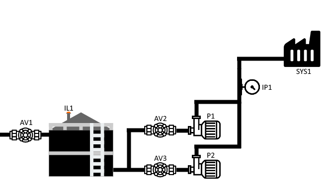
A basic 2 pump system that feeds a material into a factory process. The system is basic, with 2 direct online pumps (no variable speed control) and two upstream isolation valves. The material tank contains a level sensor and a fill valve. The post-pump pipework contains a pressure sensor and the factory process (SYS1) calls for material via a signal detailed in the below flow charts.
Assumptions / Considerations
This control scenario contains the following assumptions and considerations
- When AV1 opens, the level in the material tank will always rise
- When AV2 / AV3 opens, material will always be delivered to the suction side of P1 / P2
- P1 / P2 will always run correctly and no feedback is required
- No HMI is required (Feel free to make one if you really want though)
- No alarm management is required
- No operator input for variable setpoints is required, but the variable setpoints should be included (these are marked as bold in the below flow charts)
- You do not need to worry about electrical ratings (2A to open a valve for example). It is assumed that all digital outputs drive slave relays in a panel.
Control Documentation
This particular scenario uses Flow Charts do depict each requirement of control. There is no fixed method by which this control must be achieved, any language and style of writing can be used. It is up to you to designate IO and choose hardware.
Hardware List
- AV1, AV2, AV3
- Actuated Quarter Turn Valves – Spring Return To Close, 24vDC Signal To Open
- P1, P2
- 24vDC Output To Run
- IP1
- 4..20mA -> 0..10Bar
- IL1
- 4..20mA -> 0..5m
Flow Charts
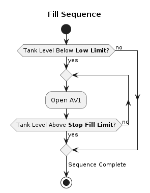
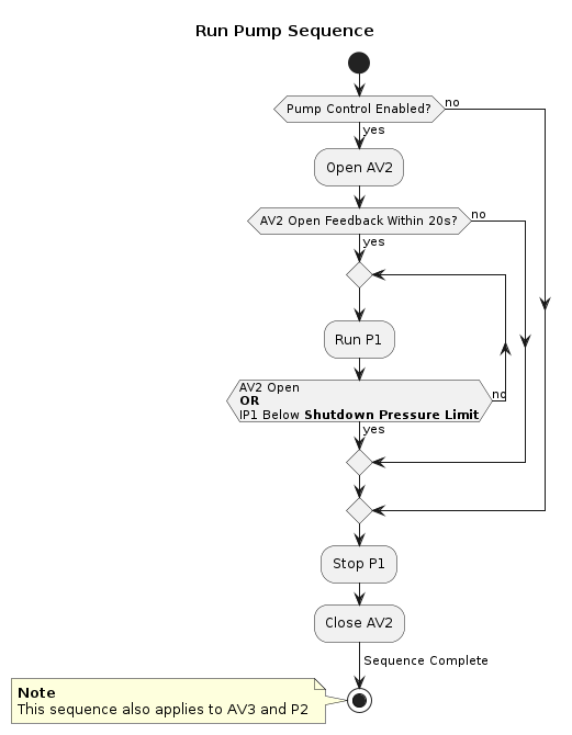
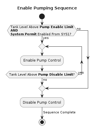
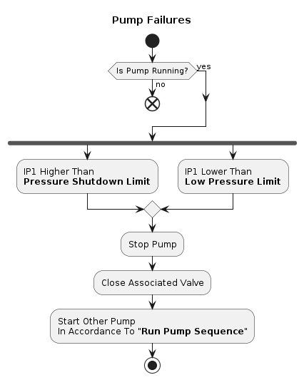
The above images are also included in the attached files on this post
🔷Download Files🔷
Note
If you require any clarification about the above control scenario, drop a comment and ask the question there. This will help everyone else too as everyone will be able to see and benefit from any answers (feel free to answer a query yourself if you can!)