Back to: Do & Grow – Siemens
This month’s control scenario is a large one, that may span over more than just November.
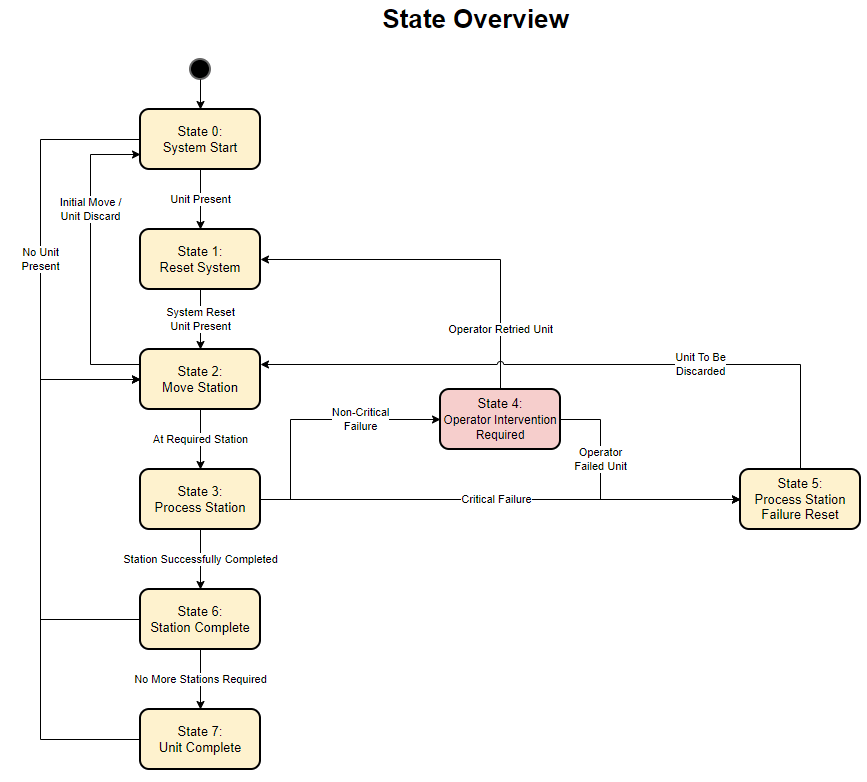
This scenario looks at a “Station System”, where a production unit is raised and lowered into different stations that perform different functions.
You’ve been supplied with the states and stations.
The system is designed so that the stations can be processed in any order or sequence via a task queue.
We’ll be calling on previous scenario experiences to put together a solution for a State Machine and associated control.
This month we’ll focus on getting the architecture for the state machine control, and then we’ll look at modifying it to include alarm and event management. Finally we’ll make produce the task queue system to make the process dynamic.
We’ll be using a mixture of languages for different “Station” control and using Ladder as the State Machine implementation language. We’re using Ladder because it’s the most commonly used and demonstrates the architecture well.
🎯What’s In This Post?
⚙️Control Scenario Data
The control scenario requirements are laid out in the state machine documentation below.
The PLC we’re using is an S7-1500 series as usual, but there are no other requirements in terms of hardware.
Use the buttons to download the control scenario, both files are the same but in different formats
📝Control Scenario Additional Information
This month, you are free to do things however you want to do them. Tips will be more guidance driven, focusing on key areas that help understand the control requirements, the architecture and introducing some new concepts such as transition management between states.
You will need to realise the IO requirements from the state machine events, to keep things simple, you can assume that a “Digital Output” or “Digital Input” is all that is required. This will be explained an built upon in the solution.
There are also some additional diagnostic requirements:
🔷Additional Control Scenario Diagnostic Requirements
- Diagnostics for the system must be available at all times
- This should include:
- Current station number
- Current state number
- Previous station number
- Next expected station number
- Time in state
- Time at station
- Fault reason
- Fault time
- This should include:
🔷UPDATE 05/12/2022
We’ll also need a digital input from each station point, to tell the system that the unit has travelled to the correct place. This can be added to the Remote IO at the appropriate station.
🆘Help
If you need any help with anything, drop a comment here, on discord or contact me on LinkedIn. I’ll answer anything you need to help you get back on track.