Timers are a staple of any PLC program, it’s extremely unlikely that any sizable project does not have a use case for a timer of any sort. This post takes us through some examples of how Timers work, use cases and also some insights into other less known areas.
What’s In This Post?
General Information
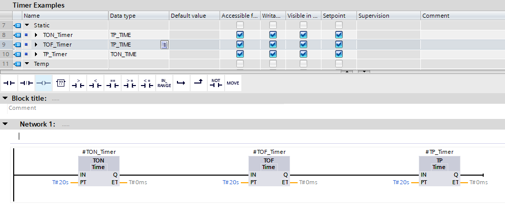
There are 3 types of timer that all have the same base type (IEC Timer), but behave slightly differently as to how they control their output.
All 3 types of Timer all share the same interface, consisting of the following:
- IN – Input –
Bool– The input that starts the timer - PT – Preset Time –
Time– The length of time the timer will run for - Q – Output –
Bool– The result of the timer - ET – Elapsed Time –
Time– The current elapsed time of the timer
TON – Timer On Delay
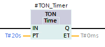
The most common type of Timer is the TON, as shown in #R1.0.
This timers output value adheres to the following logic rules:
IF
INisTrueANDETisLess Than Or Equal ToPTTHENQisTrue
ElseQisFalse
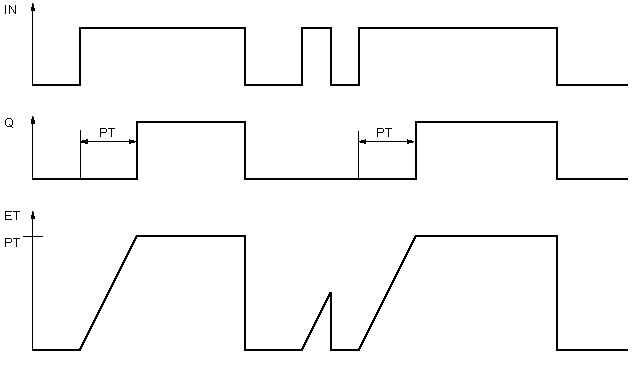
📝Note
If IN is False, ET = PT
If IN is True, ET is incremented towards the PT value
This is demonstrated in the following image, lifted from Siemens TIA Portal’s help system
TOF – Timer Off Delay
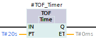
A TOF timer works the opposite way round to the TON timer, meaning the output is kept True whilst the timer is idle and not timing, but only after IN is set to True. It is on the transition to False that the timer starts.
Once started, it is not until the ET = PT that the Q value is set to False.
The output of a TOF timer adheres to the following rules:
IF
INisFalseANDETisLess Than Or Equal ToPTTHENQisFalse
ElseQisTrue
Whilst the above statement is correct, it’s important to understand that the IN must have been True at some point in order for the Q to be True. The Q output will not be true on PLC start if the IN is not True
The below diagram, lifted from Siemens TIA Portal’s help system demonstrates this:
TP – Time Period
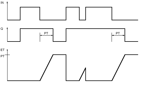
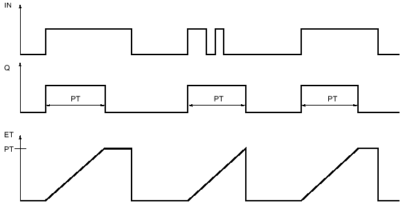
A TP timer will always complete its PT duration on the rising edge of IN. Even if IN falls to False, the timer will continue to time. During the execution of the PT duration, whilst PT <= ET, the Q is True.
The output of the TP timer adheres to the following rules
IF
INtransitions fromFalsetoTrueTHENQisTrueUNTILET >= PTEven if
INbecomesFalsewhilstET < PT, theQoutput is remainsTrueEven if
INremainsTruewhilstET >= PT, theQoutput returns toFalse
The following diagram, lifted from Siemens TIA Portal’s Help System demonstrates the above logic:
Preset Time
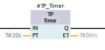
Each timer has a PT input, which sets the duration of the Timer. In order to set the PT value, the Time data type is used.
A 20 second period, represented as Time would look like T#20s when hard-coded on the interface of the Timer (See #R1.4 for example)
The PT input will also accept millisecond representations of time, for example 2000 would be T#2s. This is because the Time data type is represented in milliseconds as the base value, but visually shown as a “nice” T#2s value to keep things simple.
📝 Note
The value 7882000 as milliseconds is difficult for us to quickly work out as a time based value, so the Time data type serves as an easy way to visually read that. In this case it would be T#2H_11M_22s, which doesn’t need any further explanation
Changing The PT Value
Siemens handle IEC Timers a little differently to most other PLC vendors, opting for the rule that PT values can only be changed when Timers are NOT running. The example below demonstrates that despite the Timer’s PT value being changed from T#30s to T#15s, the Timer rolls through the 15s period, and all the way to 30s before the variable Complete is set to True
This is something that is important to understand, especially if the Timer is vital to a control function, or the PT value is dynamically assigned / calculated.
This does have an easy fix, but it is something that needs to be added for each Timer that is placed in your project.
There is a special Coil called a PT Coil. The purpose of this coil is to tell an instance of an IEC Timer to re-calculate the End Timestamp that the ET is expected to reach the PT. When the PT Coil is set to True, the instance of the Timer used will be updated and the timer will behave as expected.
The below example now behaves as we’d expect, stopping at T#15s now there is a PT Coil in use
📝 Note
Notice that in example #R1.7, when changing the PT value from T#30s to T#15s, the Timer stopped at T#15s as we’d expect. Also notice that once the Timer completed, setting the PT value back to T#30s, before 30s had elapsed since IN became True did not set Q back to False. This is because once Q is set to True, the Timer is unable to load a new PT value until the IN transitions back to False
TON_Time, TOF_Time and TP_Time Data Types
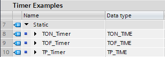
Each Timer type has its own instance data type, as shown above. This means that TON uses TON_Time, TOF uses TOF_Time and TP uses TP_Time.
However, a not-so-well-known secret of TIA Portal is that all of these timer instance data types are actually an alias for the data type IEC_Timer. You can actually mix and match all of the Timer types with any of the data types, and the project will compile and operate without issue.

TP_Time instanceThe above image shows that a TON timer has an instance declaration as a TP_Time data type, yet is operating as a TON still. If it were to behave as a TP, we’d expect to see the Complete variable as True.
Creating a Multi-Ability Timer
Because of this, we can exploit the fact that all timer types can use the TON_Time data type to create a 1 Timer Fits All super Timer.
This timer will be capable of the following functionality:
- No need for a PT coil – PT values will update the expected ET output every single time
- Mode Input – The timer can be configured as TP, TOF or TON on the interface of the block, or even programmatically
- RT output – Remaining Time output, a backwards countdown version of the ET
- Formatted time output – An easy to view and pass to SCADA version of the ET or RT
What’s interesting about this approach is that this TON_PT Function Block is capable of running in TON, TOF and TP, but only has 1 instance of a Timer declared in the Static scope.
Logic Walkthrough
This section will walk through the logic, network by network.
NW1 – Initialize Timer Outputs
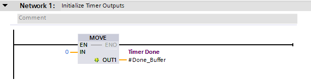
This network ensures that the USint variable Done_Buffer is set to 0. Because of the AT Constructor in use, all Done_Bits in the Array[0..7] of Bool are set to False
NW2 – Allow For Async Updating Of PT Value
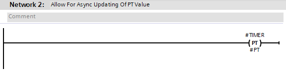
The PT_Coil used allows the TIMER instance to be updated with a new PT value should one be passed through the interface
NW3 – Router TON
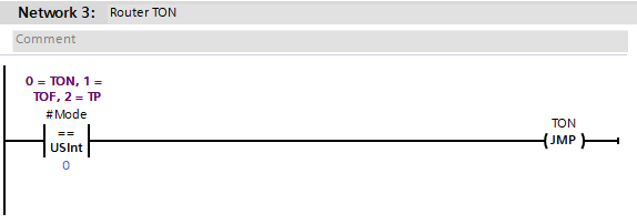
This network utilizes a JMP command, to jump to the label TON further down in the block.
NW4 & NW5 – Router TOF and Router TP
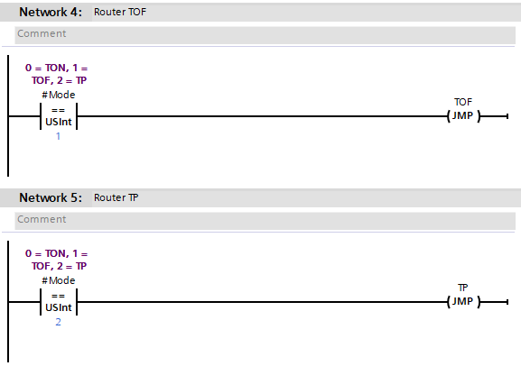
Similarly, the above networks jump to the appropriate label depending on what Mode is set to
NW6 – Call TON
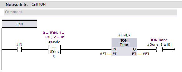
Using the interface variables, the TON timer is called as normal, with the output Q variable being passed to the Array (Done_Bits[0]).
📝 Note
Note the TON label on this network. This tells the JMP command used in #R1.14 to jump to this network
NW7 – Continue
This is another JMP command that jumps to the CONT label later in the block
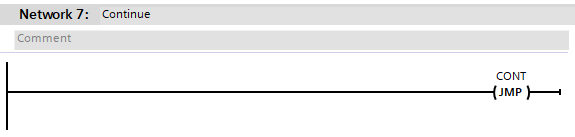
NW8, 9, 10 & 11
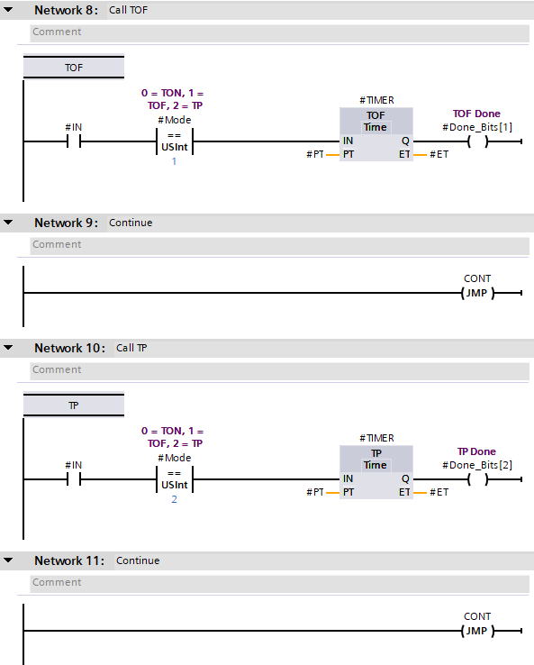
The same is repeated for the TOF and TP calls.
Make note of the fact that TOF and TP use different Done_Bits, and both networks immediately after the calls to Timers call the JMP to CONT command.
NW12 – Time Format Management
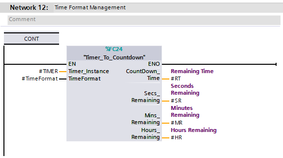
This is a special and custom Function that takes the instance data (TON_TIME in this case) and calculates the RT, SR, MR and HR values. The logic behind the block is simple maths:
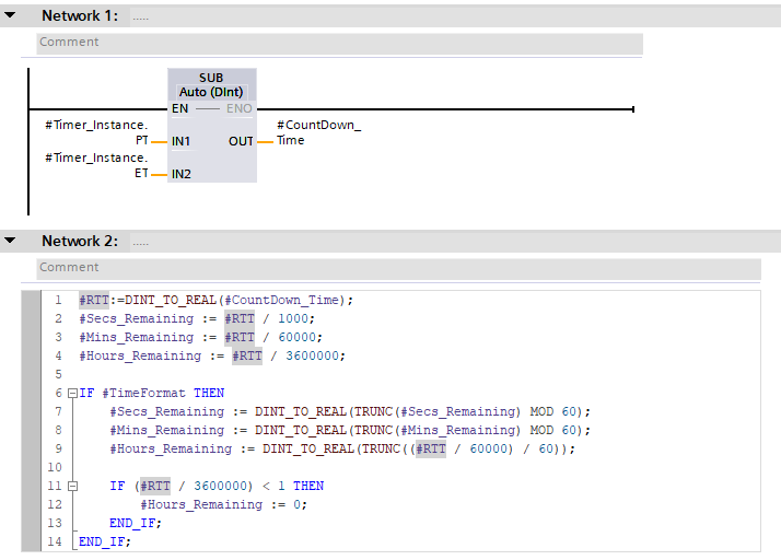
Timer_To_Countdown block calculationsNW13 – Output Management
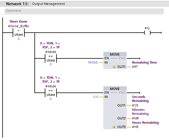
The final network manages the Q output, as well as managing the expectation for RT, HR, MR and SR depending on the mode that is in use.
📝 Note
Because of the AT Constructor, the Done_Buffer will have a numerical representation of the Done_Bits Array. This means that if any element within the Done_Bits Array has a True value, the Done_Buffer will have a value larger than 0.
Considerations With This Approach
The Mode value should not be changed whilst the Timer is running! This could cause issues with expected output (Q) values.
Because the JMP commands stop any interaction between different timers, we are safe to re-use the same instance of TIMER with 3 different Function Blocks. We know that only 1 can be scanned at any one time.
Try Yourself
Do & Grow members should have a go at creating this type of Timer themselves, with additional functionality that suite their own needs!
well Done!
Hi Liam, i am struggling a bit with the SCL part of this, could explain in more detail on how this is structured. Thanks
Are you referring to R1.20?
If so, then the following is occurring:
1. The `RTT` tag holds a REAL version of the PT value (with the ET subtracted). It needs to be a REAL value so that division can take place and the decimal part of the result is held
2. Secs, Mins and Hours remaining variables are simply the `RTT` value divided by appropriate values to get the represented time period.
3. If the variable `TimeFormat` is TRUE, then the Secs, Mins and Hours variables are subjected to additional calculations where by the MODULO mathematical expression is used to calculate only the remainder. The TRUNC function is used to remove the fractional part of the REAL (which also converts to DINT, hence converting back to REAL using DINT_TO_REAL). The additional IF statement handles the MODULO of hours always returning 1 if less than 1, so we always round down to 0 in that case
The end result of the `TimeFormat` would mean change Case A to Case B:
Case A – `TimeFormat` = FALSE:
Seconds = 8092
Mins = 134.86
Hours = 2.25
Case B – `TimeFormat` = TRUE:
Seconds = 52
Mins = 14
Hours = 2
Case B can then be re-arranged on SCADA / HMI to a time stamp of: 2h 14m 52s
Hope that helps!