[membership level=”-1″]
Membership Required

Do & Grow members benefit from additional access to particular articles and downloads in addition to the more scenario based learning. You’ll need a Do & Grow membership in order to access this content
What About Gold Membership?
To simplify the process, gold membership is being brought into Do & Grow, so the two are combined. If you’ve already purchased gold membership, you can get the first 2 months of Do & Grow for free by contacting Contact@liambee.me and providing your email address. You’ll be given a discount code for Do & Grow that will allow 2 months access.
[/membership]
What’s In This Article?
[membership level=”1″]
Overview

Simulation of assets within a project can be achieved in multiple ways, especially by spending money on tailored packages from manufacturers / automation vendors. However, you can provide basic simulation yourself by implementing a Simulation Layer, Input Mapping Layer and Output Mapping Layer.
These areas work together to “trick” the main PLC program into thinking raw values are originating from the IO, or real devices, when in fact, they are coming from a different source entirely. The different sources your simulation data could come from depends on what you are trying to achieve, but in its most basic form, it will simply be a representation of the Raw value that is injected in the real assets place.
Consider the diagram R1.0 above, this shows that we have an Asset Signal that is used when the Master Hard Sim value is False. However, when Master Hard Sim is True, the Asset Signal is replaced with a value from the Hard Sim Values Data Block. It is at this point that the signal is now simulated.
Consider what happens to the Asset Signal in the Input Mapping Layer too. When something is Mapped, a movement of information occurs. This layer moves Raw data into Asset data. So when something is simulated, we simply move the simulated data into the Asset data for the project, instead of the actual raw data from the asset itself.
Creating Simulation Points

Bool data with simulationBy creating standard objects that handle both the Mapping of data from your hardware, and also the Simulation entry points, you can develop approaches that are both reliable and reusable.
Image R1.1 above shows this in action. There are 4 key areas to this type of mapping Function
- Simulation Switch
- This tells the function whether or not it should be mapping the
Input_Dataor theSim_Datato theReal_Data
- This tells the function whether or not it should be mapping the
- Input Data
- This is the data from the Input Hardware
- Real Data (Asset Data)
- This is the data that the project will use, its the end point for both the
Input_DataandSim_Data, depending on which one is in use
- This is the data that the project will use, its the end point for both the
- Simulation Data
- This is a simulated copy of the
Input_Data. In this particular case, its aBooldatatype because this function simply maps a singleBoolvalue.
- This is a simulated copy of the
The Sim Data must either be exactly the same as the Input data, or be a structure that contains the same as multiple Input Data variables.
Managing Multiple Inputs In One Function

In the case of R1.2, more than 1 point of data is passed through the interface. The principle is still the same as a single point though.
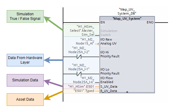
If we look inside the Function Block Map_UV_System, we can see how the simulation is managed:

The image above, R1.3, shows how more than one data point is managed inside this mapping function block. It simply performs the mapping and simulation functions twice, but with different variables and output points.
📝Note
R1.3 uses R_UV_Data and S_UV_Data. The R denotes the Real Data (the data used in the project) and the S denotes the Simulation Data
Complex Simulation

Simulation environments can be made as complex or as simple as you need. The image in R1.4 demonstrates this by creating an Auto Feedback system.
The Function Block Diagram shows that if the Simulation Switch, Auto_Feedback and Run_Output_To_UV_System are all True, then a Timer is started. Every time this timer completes, the Simulated Raw_Analog value is incremented by a set value.
This gives the effect of the intensity measurement asset ramping up its signal when the Real Data in the project is asking for the system to be run.
This creates a Closed Loop Feedback system, where actions of the main project drive our simulation system to imitate the behaviour of the real asset.
The project does not understand, or know, the difference between real data and simulated data, so it’s a great way to test your own controls.
Managing Data In Simulation Areas

UDT structures that manage themIn order to effectively manage your simulation and mapping systems, using UDTs (User defined structures) is a great way to ensure that data exists in the same way each time.
Image R1.5 above shows that the Map_UV_System function block uses 4 I/O variables to capture data from the Hardware Layer. Inputs are always for the data from the hardware layer in this case.
There are no Outputs from this Function block because we’re not looking to interact with the data at his level, we’re just looking to map the data into the Real Data structure.
The InOut data contains both the Simulation Data and the Real Data. The Simulation Data should consists of the same data variables as the Input to the Function Block in which the data is being used:

If you look at image R1.5 at the Input area, and then look at the above image (R1.6), you can see that both contain:
- Raw Analog UV
- Hi Priority Fault
- Lo Priority Fault
- Flow Enabled
These are the 4 inputs that the real, in-field asset provides to the PLC hardware. The Auto_Feedback variable is used by the simulation system to activate any automatic feedback requirements that may or may not be available.
By ensuring that a dedicated UDT is used for the Asset Simulation Data, it means that we can “Mix and Match” different data sets in the same DB, keeping things neat and contained:

UDTs in use.Once you have built the framework for simulation, managing the data and simulation functions is simple and easy to do. You’ll get used to dropping mapping functions into a set area, tagging up your inputs and then providing simulated data to allow for easy manipulation during testing.
Interacting With Simulation Data
There wouldn’t be much point in having the simulation data if you weren’t able to interact with it. Manually changing values in the Simulation Data block (like in R1.7‘s image) is all well and good, but it means that non-programmers aren’t able to use the simulation system at all.

Creating a soft HMI (one that will only ever be used running on a PC, rather than being downloaded to hardware) is one of the easiest ways to provide some functionality with your simulated environment.
Image R1.8 shows an example of Faceplates being used to tie in to UDT structures of various types. For example, IL403 is an Analog Device, the faceplate only allows it to be used with an Analog UDT.
This approach means that everything slots together like a jigsaw, and it’s impossible to use the wrong structures, faceplates and simulation environments with the wrong assets.
Similar to the Functions and Function Blocks that can be used to manage the simulation / mapping, the Faceplates can be as complicated as you need them to be

UDTThe above shows how each element on the Faceplate connects to a point within the UDT_Map_VSD_Drive V0.1.0. We then provide the Faceplate Instance with the corresponding tag in the PLC.
This then allows the Faceplate to directly control the Simulation Data that is being mapped to the Asset Data, which in turn affects our project’s behaviour based on the logic that we’ve written.
Automating Simulation
There are lots of different ways that this can be achieved, but the most simple is to provide a check that states:
If Simulation is active, and automatic simulation is active, then update simulation values according to some logic

Auto_Feedback provides the method of updating feedbackR1.10 Shows a very basic form of automated simulation. When the Simulation_Switch is True, and the Real Data (Asset Data)’s Start_Request_To_VSD_Hardware is True, the Contactor_Feedback in the Real Data will be set to True. This only occurs if the Simulated Data’s Auto_Feedback is set to True.
This type of Automated Simulation is designed to reduce the need for manual intervention when testing systems. You can test, with Auto Feedback turned off, that the contactor feedback discrepancy is working correctly and then turn Auto Feedback on and never have to worry about the signal not being on when it should be, as the system takes care of itself.
Network Simulation
You can choose to get as complex with your automation as you wish, opting to expose your Simulation Data to a network protocol such as OPC UA or Modbus. You could even directly connect using the S7 protocol with Siemen’s TIA Portal Openness

Once you’ve built the infrastructure for these types of connections, you can take the automation of your simulations to a completely different level.
R1.11 demonstrates using C# with Siemens libraries to connect to a PLC, read available tags and modify them. Here we can see a sequence being built where by a Hand_PB is set to True and then the Hand_IND variable is read for an expected result.
The sequences are flattened out into JSON for storage and retrieval so that different sequences can be saved and loaded for use later against different projects.
📝 Note
This particular example has not been finished and is very proprietary to how my projects are set up, however the principles remain that you could build your own testing system that interacts with your simulation data, utilizing structured data in the way you have designed
Key Takeaway…
For this entire system to work the correct way, be expandable, flexible but also remain standard, is to ensure that it is based on Structure.
The easiest way to do this is to use UDTs and Faceplates in HMIs.
Remembering why we’re offering simulation, and the simplicity behind it’s requirement is important. In nearly all cases, simulation of a signal (raw simulation) is not required once commissioning and testing is completed. Nearly all instruments and assets have methods by which their output can be tested, and you have the opportunity to override your scaled value and control methods in your main logic should you need to.
Keep it simple, but understand how to make it complex if you need to!
[/membership]
Check Out Another Post

PLC Basics – Structuring Project Flow
No matter what environment you use to develop your PLC, structuring project flow is important to ensure an easy to…