Back to: Do & Grow – Siemens
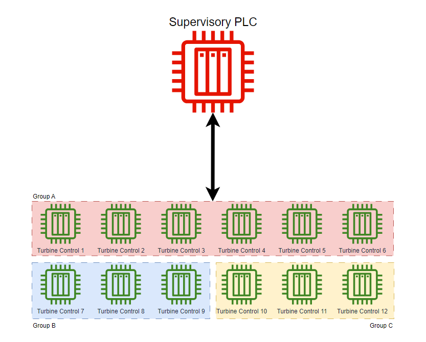
In this scenario, we’ll explore the concept of Supervisory Control. This is when local PLCs are used to control a dedicated process, but are governed by a Supervisory PLC.
In essence, this can be referred to as a Master/Slave configuration. The slave PLCs (Local Turbine Control) are tasked with actioning control over the turbine process. The master PLC (Supervisory PLC) is tasked with managing the entire process, including monitoring each local PLC and issuing commands for local PLCs to act upon.
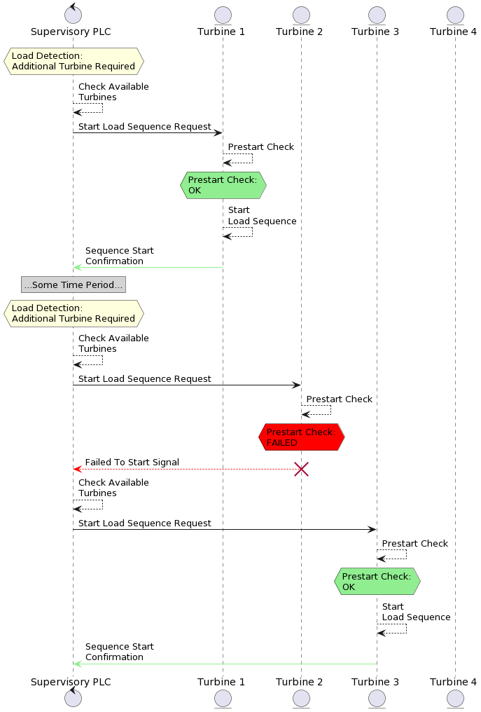
In the above sequence diagram, we can see that the Supervisory PLC is responsible for managing the Load Detection of some upstream process. When the load is detected as High, the Supervisory PLC then checks for availability of turbines and issues a command to start the “Load Sequence” to a particular Local PLC.
The Local PLC‘s responsibility is to listen for this request, check it’s own availability to start and report back whether or not the starting of the sequence is successful or not.
Control Scenario Design Specification
The design specification behind this control scenario is very simple and can be detailed in a straight forward flow diagram:
Supervisory PLC Control Requirements
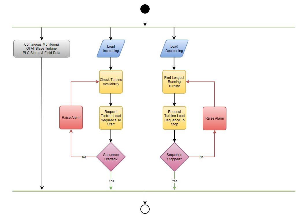
This diagram shows how the Supervisory PLC is responsible for the following:
- Monitoring System Load across different groups
- Calling for a Turbine to start the Load Sequence
- Calling for a Turbine to stop the Load Sequence
- Raising alarms if a Turbine reports it failed to start
- Raising alarms if a Turbine reports it failed to stop
- Monitoring runtime of each Turbine
- Continuously monitoring the PLC status of each Turbine station
- Continuously monitoring the field data of each Turbine station, the following signals are monitored
- Turbine Load (%)
- Turbine RPM (RPM)
- Turbine Temperature (°C)
- Turbine kWh (kWh)
- Turbine Status Signal (Byte)
- Communication Pulse (X0)
- Sequence Status (X1..X4)
- 0 = Idle
- 1 = Prestart Check Active
- 2 = Starting Load Sequence
- 3 = Ramping Turbine
- 4 = Load Sequence Active
- 5 = Shedding Turbine
- 6 = Load Sequence Stopping
- 7 = Post Run Cool Cycle (Unavailable)
- Healthy (X5)
- Available (X6)
- Monitor average Turbine load across different groupings, raising alarms if any groups load exceeds 75%
📝Note
The Local Turbine PLCs are not part of the development in this control scenario. The focus on this control scenario is understanding the best way to repetitively check data from multiple sources, manage multiple sequences at the same time and create the supervisory PLC in a way that is can easily be expanded for more local PLCs
Getting Started
There are key concepts that need to be considered for a solution to this scenario
- Communication layer
- What is the best way to obtain information from multiple downstream PLCs that are all identical?
- What needs to be configured in the hardware layer?
- Structure
- Where can UDT’s and Structs be implemented to ensure the easiest and simplest code for managing data?
- Where can UDT’s and Structs be implemented to ensure the easiest and simplest code for managing data?
- Language
- What would be the best language to use for this?
- What would be the best language to use for this?
- Data Blocks
- How should the data be managed in the Supervisory PLC? Do we need to store any Turbine data?
Coming Up…
The next post will provide a template to get started, it’ll be basic, but will give some insight into how this sort of thing should be approached.
For now, get started yourself and see how your start approach to this compares. There’s so many different ways a solution to this problem could be achieved!