[membership level=”-1″]
💷 Membership Required For Full Post Content
This post contains content that is omitted for visitors that are not members
[/membership]
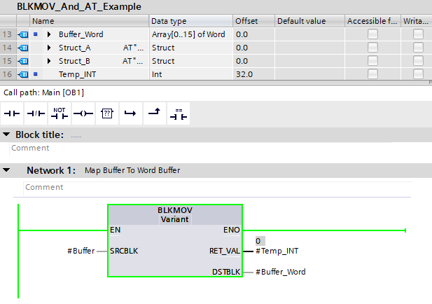
The BLKMOV and AT constructors can be used to manage moving data from one data type to another. This can be useful if you are managing buffered data, or data from a network protocol such as Modbus, where all data is sent in packets of Words
📝Note
For both the BLKMOV and AT constructor, block optimization must be set to FALSE
What Is BLKMOV
BLKMOV is similar to the MOVE instruction, except the data type of the input does not need to match the data type of the output. The length of the data doesn’t need to be same either, although truncation will occur if they are not the same and the output area is smaller.
The only rule is that the source area and the destination area do not overlap. Booleans also have to be managed carefully, ensuring the boolean area is divisible by 8… Basically, don’t try and pass single booleans through the BLKMOV instruction.
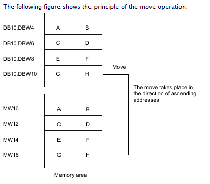
The above image shows the basic principles of the BLKMOV, however it’s not particularly clear. Here’s a better one:
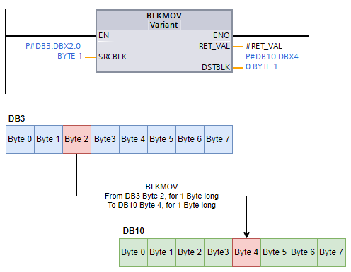
This shows that the BLKMOV instruction is pointing to Byte 2 in DB3 for 1 Byte long. This is then being moved into Byte 4 in DB10, again for 1 Byte long.
You can also use Symbolic Access instead of pointers. TIA Portal will automatically create the necessary pointers for you.
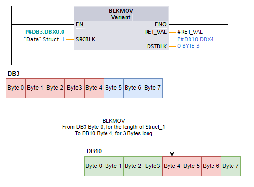
Notice that the "Data".Struct_1 has an address above it that is constructed as a pointer – P#DB3.DBX0.0. No length is specified as it will be the length of Struct_1.
In this case, Struct_1 is 5 bytes long, the area we’re trying to move it to though is only 3 bytes long. This will still work, but the last 2 bytes of the Struct_1 data will be lost.
It’s important to understand that the actual data type in these areas may not be Byte, but could consist of other data types:
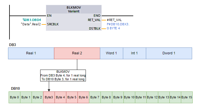
The above shows us moving a Real value into 4 bytes. As long as the data length matches, this will not cause any issues
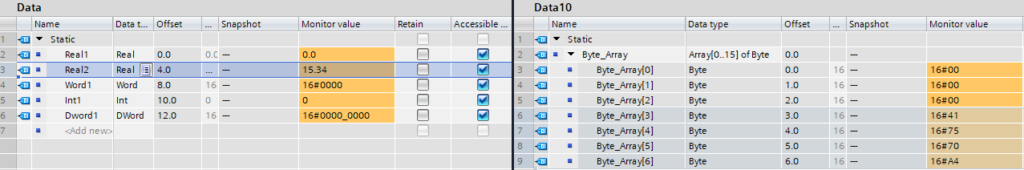
The above shows the Real2 value of 15.34 being moved via BLKMOV into the DB10 - Data10 block at Byte 3 for 4 bytes long.
AT Constructor
The AT constructor is a special instruction that is typed into the Data Type field before choosing the actual data type you need. It allows the overlapping of symbolic references with the offset in memory allocted.
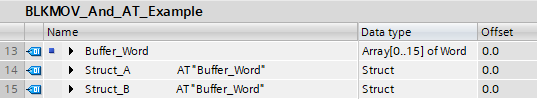
Notice that in the above image, all 3 of the variables have the Offset of 0.0.
Struct_A has the constructor AT "Buffer_Word", as does Struct_B.
The way this works is that when you use the AT constructor, the variable above is what is used as the reference, unless it is already using an AT constructor, in which case the reference moves up 1 row.
You are not able to choose what variable the AT constructor points to, it simply references the variable above.
In addition to this, you can only use the AT constructor in the Temp variable scope:
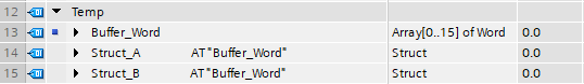
This means that you will have to copy any Input or InOut variables to temporary memory before being able to use this approach:
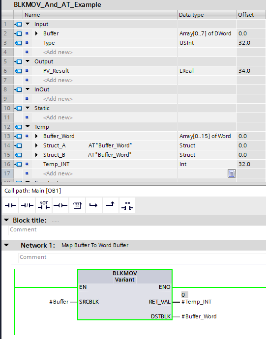
The above image shows that the Buffer variable on the Input scope is moved to the Buffer_Word variable in the Temp scope.
In doing this, Struct_A and Struct_B are also populated with data, since the reference the same memory point (offset 0.0)
We can then use Struct_A and Struct_B as if they are normal variables:
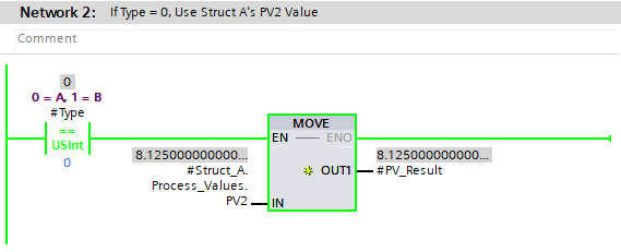
For example, this network is checking if the Type input is 0. If it is, then Struct_A.Process_Values.PV2 is used and passed to the output.
However, if Type equals 1, then the following is done:
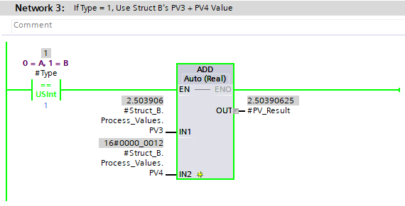
In this case, Struct_B.Process_Values.PV3 and Struct_B.Process_Values.PV4 are added together before passing to the output.
The information passed in on the Buffer input has not changed between the two scenarios:
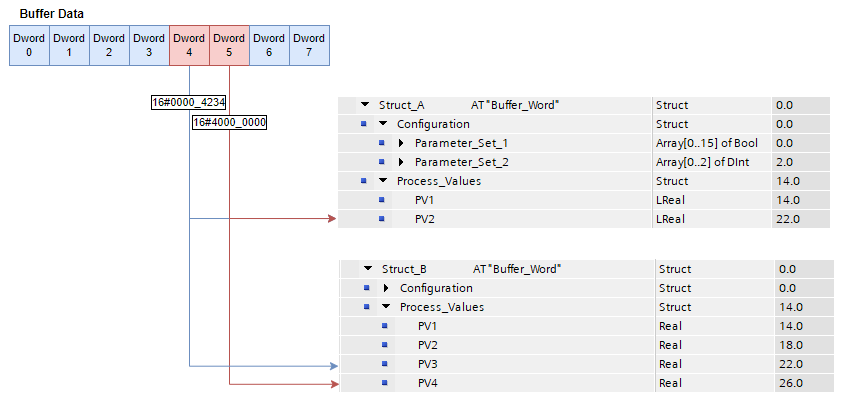
The above image shows that the Buffer data is made up of 8 Words. Remember that this is being BLKMOV‘d into Buffer_Word (16 Words).
This data is then layed over the two structures as pictured. Struct_1 uses LREAL data types for process variables, but Struct_2 uses Real data types, which are half the size. The overall length of both structures is 32 bytes.
A Dword is 4 Bytes long, so for Struct_A, both Dword 4 and Dword 5 are moved to PV2 as LREAL is 8 Bytes long. But in Struct_B, each Real is 4 Bytes long, so the Dwords from the Buffer are stored in PV3 and PV4, changing the usage of the data.
Download Project Example
You can download the project that was used in the images in this post below.
This file can only be downloaded by Do & Grow members, you can enroll below and benefit from other great content!


I have no access to the Software example.
Hi Marcelodias99,
Fire me a message on LinkedIn / Discord and we’ll sort this out (Do & Grow members are entitled to a free Gold Membership, but you must activate it yourself)
How to get access to the files?
Apologies, this page had been missed as part of the update. You need to be a Do & Grow member in order to download the example project. The membership detail checks have been updated to the new version now