
Put/Get communication is very common in TIA Portal applications where more than 1 Siemens PLC is involved.
It’s simple to set up, easy to work with and uses the S7 Protocol, meaning there’s no nasty surprises
🎯What’s In This Post?
⚙️How To Configure Put / Get Communication
The guide below is a simple example of setting up communication between two S7-1511 PLCs.
Both of these PLCs are running TIA Portal V17 – Firmware V2.8 (Simulated)
The application in the example is as follows:
- PLC_1
Getsdata from PLC_2 - PLC_1 updates the data
- PLC_1
Putsdata into PLC_2
The above cycle repeats, incrementing a counter. Essentially we’re using PLC_1 to increase a counter variable in PLC_2.
⚡Initial Setup
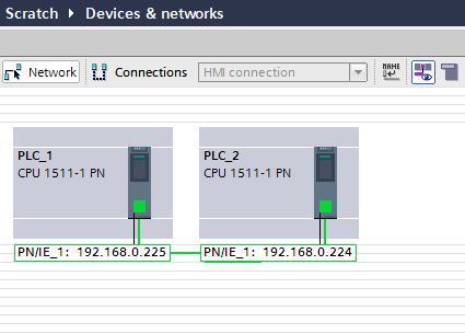
To begin, two PLCs need to be added to your project.
In the Devices & Networks section, the two CPU’s should be connected together with a Profinet network (in this example, it doesn’t have to be Profinet)
Once this has been completed, an additional connection needs to be made. Click the Connections button near the top of the Devices & Networks window. From the dropdown, choose the S7 Connection
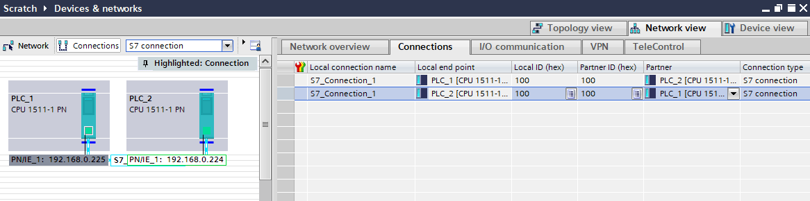
Drag a connection between the two CPUs.
In the panel to the right of the screen, you’ll see two new connections with the same name. Once for PLC_1 and the other for PLC_2. In this case, TIA Portal has assigned both of them the local ID (hex) of 100.
🔁Setting Up Data Transfer
Now that we have the device hardware set up the way we need it (nearly, see below!), we now need to actually start looking for some data to move around…
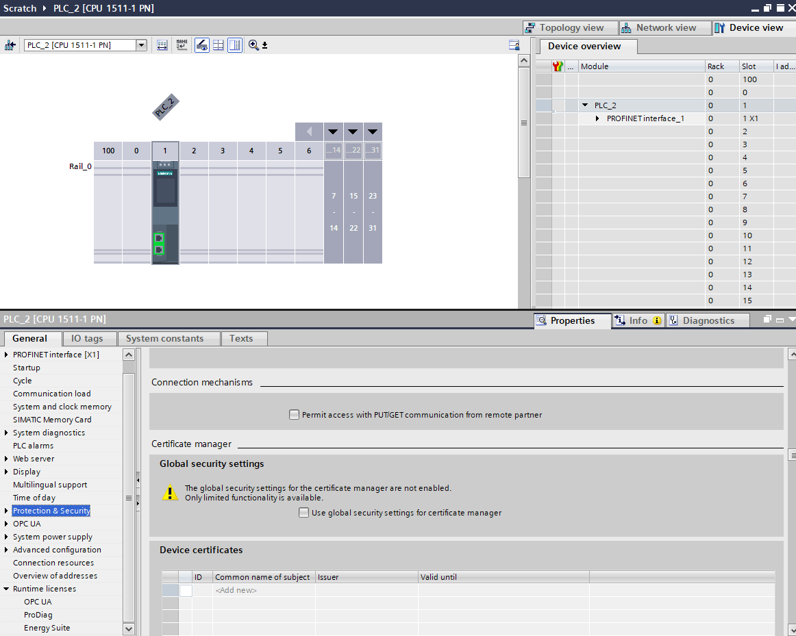
Before you leave the Devices & Network screen, edit the device settings for each CPU so that Permit access with PUT/GET communication from remote partner is checked. This is unchecked by default.
🧠GET Logic
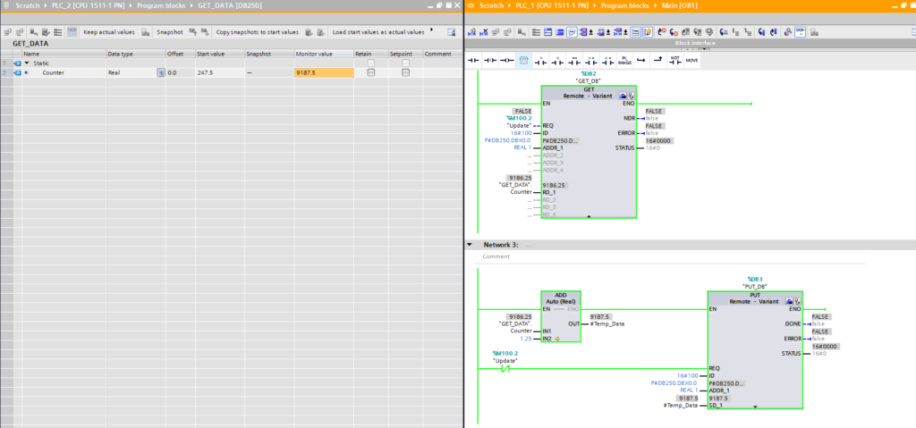
In our Main (OB1) object, I’ve simply placed a GET function block as pictured below.
Note: Because this is in OB1, an instance data block is required (DB2)
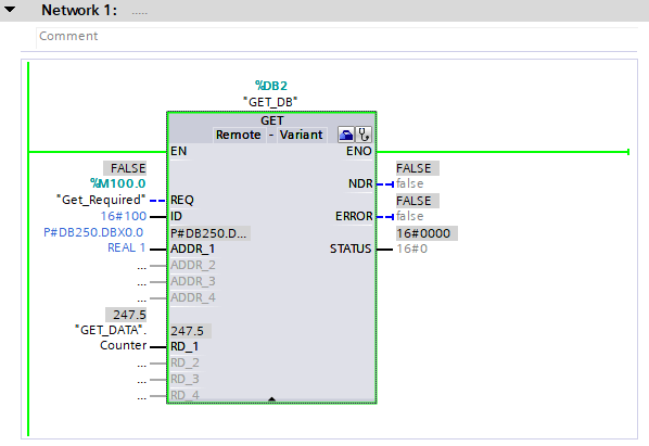
The interface is composed of the following items:
- REQ – Requirement to GET data from remote partner
- ID – Hexadecimal ID of partner (16#100 in this case)
- ADDR_1 – Pointer to address of partner
- RD_1 – Pointer to address of receive data location
If you haven’t worked with pointers before, I suggest you check out the following post
In order to get data from the remote partner (PLC_2), the interface ADDR_1 is populated with the Data block location and the Data location. In this case, this is DB250 and the first element, which is a REAL
It’s a good idea to control when the PUT/GET REQ input is used. Pulse it cyclically instead of setting it to just TRUE
If we had mixed data and wanted to grab all of it, as long as the data length encompases everything we want to obtain, it would all come across in the pointer
For example, P#DB250.DBX0.0 BYTE 4 would still grab the same data as the P#DB250.DBX0.0 REAL 1, as a REAL is 4 BYTES in length.
🔹Optimized Data
The remote location cannot have optimized data, else the data will not be obtained, or could return the wrong information.
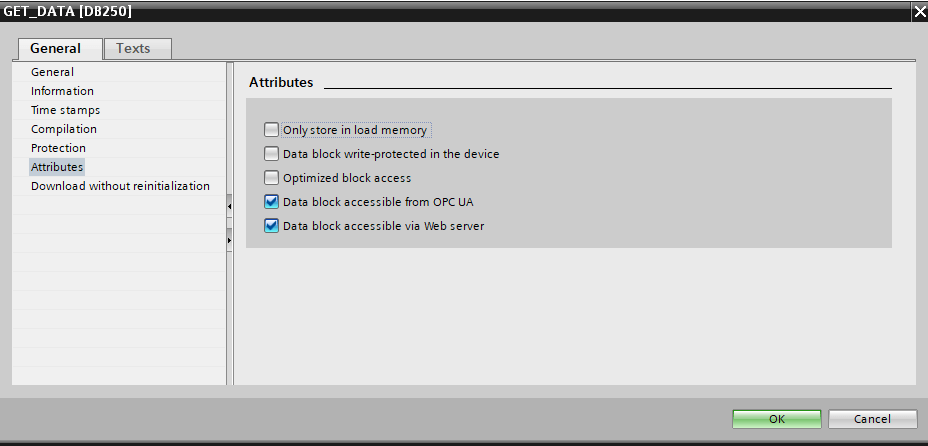
False in CPU 2 (Note this is DB250 in PLC_2)It’s probably a good idea to just set all DB’s that are related to PUT/GET to False for optimized data
🧠PUT Logic
The interface for the PUT function block is largely the same as the GET function block, however we’re transfering from PLC_1 to PLC_2 in this case.
The SD_1 interface sends the data to the ADDR_1 location in the remote partner
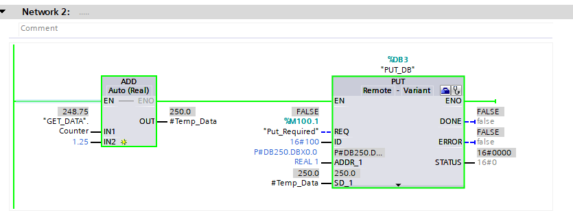
The above image shows that we’re adding 1.25 to the contents we’ve read from CPU 2 and stored in CPU 1‘s GET_DATA.Counter. Once the addition has taken place, when Put_Required is set to True, the data is sent to the same register in CPU 2 that the GET block is reading from.
📽️Full Example
By adding a Flip Flop timer setup, we can call both the PUT and GET function blocks in sequence, obtaining data, modifying it and placing it back in PLC_2
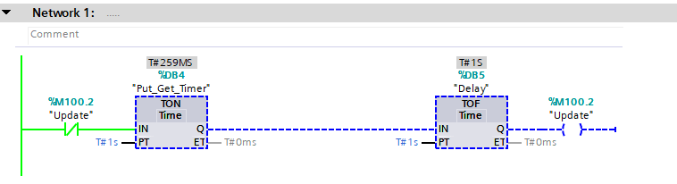
The above image shows how the update Flip-Flop arragement is working
📽️Video Example
You can see from the above video that the PUT updates DB250 in CPU 2 and then 1 second later, the GET pulls the information back into CPU 1 and the cycle repeats itself.
🗝️Key Points
- Ensure both CPUs have PUT/GET enabled
- Ensure an S7 Communication link exists between the CPUs
- Cyclically call PUT/GET
- Ensure the correct ID is used
- The pointers must point to the correct location, one in the local PLC and the other in the remote partner (ADDR_1)
🗃️Project File Downloads
Download the V17 example project and PLC_1 / PLC_2 PLCSIM Advanced Virtual SIMATIC Memory Cards used in this post
[membership level=”4,1″]

[/membership]
[membership level=”-4,-1″]
⚠️ Membership Required

🔒What Am I Missing Here?
Download links for Project and Virtual PLCSIM PLC files
[/membership]