Looking to get started with Ladder Logic?
Here’s an introductory guide to the PLC language that is not restricted to a single development platform or environment
Although most of the images use Siemens TIA Portal, the rules of the language will still apply to Allen Bradley, Codesys (and all flavours of Codesys) and many other PLC development softwares.
As always, if you want to discuss further, drop me a message in the comments or on LinkedIn
Basic Principles
Ladder Logic, often shortened to just “Ladder”, is the most popular language used in PLC programming. Almost all development platforms utilize it and nearly every PLC software engineer is expected to understand it.
The uptake of Ladder has been so successful because of its very visual and basic design.
Flow
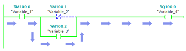
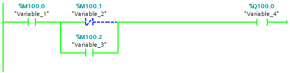
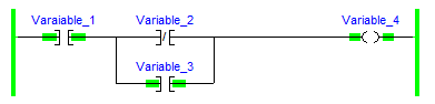
The image above demonstrates Flow. This shows how the logic that is being processed flows from the left of the network through to the right.
Variable_1 and Variable_3 are both Normally Open Contacts, represented symbolically by an open break in the logic line. Variable_2 is a Normally Closed Contact, represented symbolically by a closed break in the logic line.
Because Variable_1 and Variable_3 are both True, logic is allowed to flow through it to Variable_4, which is a Coil. Coils write a True value when the preceding logic is true and a False value if the preceding logic is false.
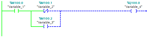
In order for the Variable_4 to be True, Variable_2 must be False, OR Variable_3 must be True. This is because Variable_2 and Variable_3 are branched, creating multiple routes for the logic to travel. Remember that Variable_2 is a Normally Closed Contact, so allows the logic through when the variable assigned to it is False
Not all environments display flow the same way. In Allen Bradley, the flow is highlighted on instructions only, and not between them. This makes things harder to read in my opinion.
When it comes to multiple networks in a Ladder logic code, (Block, POU, Routine… the name of what defines a section of code changes depending on the environment you are working in) the rules are the same. The logic flows top to bottom, visiting each rung and executing each rung from left to right:
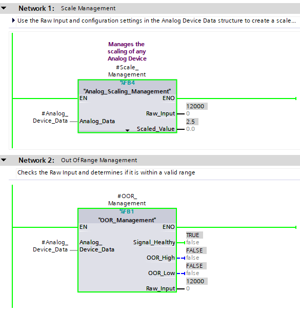
The above example means that the Analog_Scaling_Management Function Block on Network 1 is called first, followed by the OOR_Management Function Block on Network 2
Box Instructions
In addition to the standard Contacts and Coil instructions, there are also Box Instructions. These are typically either pre-built functions provided by the environment that you are working in, or instances of Function Blocks or Functions
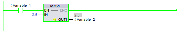
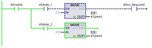
The above image shows an example of a Contact enabling a Move instruction to move the value of 2.5 into Variable_2
There are some rules around where Box Instructions can and cannot be used. For example, you are not allowed to branch around another Box instruction if the branch in question is not connected to the Power Rail on the left side of the logic (Siemens TIA Portal):
Allowed Configurations
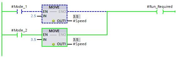
Box Instructions that exist on branches connected to the Power Rail are permitted
Disallowed Configurations
The branch is not allowed to rejoin the main branch if a box instruction exists that is not connected to the Power Rail
In different editors, different rules apply. For example, in CODESYS, the below is perfectly acceptable

Function Blocks
Calling Function Blocks in Ladder is the same as calling a Box Instruction, except you call an instance of the Function Block you need
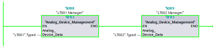
The above shows a Ladder network calling two different instances of Analog_Device_Management.
The LT001 Manager instance and the LT002 Manager instance both use the Analog_Device_Management code within the Function Block, but use different datasets. In Siemens TIA Portal you can see this denoted by the %DB8 and %DB9 above the two Box Instructions. This means one is using Data Block 8 and the other is using Data Block 9.
Parameters are passed into the Function Block through Interface Pins. This can be seen above, with the Analog_Device_Data interface being populated with "LT001".Typed and "LT002".Typed respectfully.
Nearly all PLC environments work in the same way:
Allen Bradley Studio 5000
CODESYS V3.5
In all 3 environments looked at, all 3 have the same basic principles:
- Function Blocks are called in the same way as all other Box Instructions
- All have an interface where parameters are passed in (and out) of the Function Block
There are some differences too
- CODESYS can call Function Blocks with or without the EN and ENO connectors
- When EN is TRUE, the Function Block is processed
- ENO is typically TRUE when EN is TRUE, however can be set to FALSE internally
- Siemens TIA Portal always calls Function Blocks with the EN and ENO connectors. The result of ENO depends on the contents of the block, the language it is written in and the configuration of error handling
- Allen Bradley do things differently and Function Blocks don’t truly exist. Instead, Addon Instructions (AOIs) are used. Whilst these behave the same in essence, they don’t have the same flexibility as Function Blocks.
- These do not get called with EN or ENO, but behave in the same way if the logic preceding the instruction is FALSE.
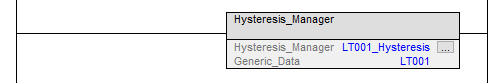
Functions behave in the same way as Function Blocks and are called using the Box Instruction method.
Basic Examples
It’s often easier to get to grips with a language when you have some basic examples to follow.
The below examples come from Siemens TIA Portal, Allen Bradley Studio 5000 and CODESYS 3.5, but will be valid in nearly all other environments once any slight variations to layout are taken into consideration.
Latching Contacts
There are various ways to achieve a Latch in Ladder Logic, including built in methods such as the Set Coil:
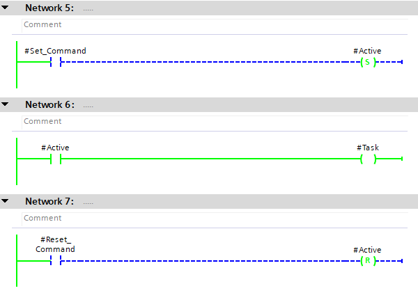
The above example’s current state shows that the Task variable is TRUE, even though the Set_Command variable is FALSE.
This is because the Active coil on Network 5 is a Set Coil. Once a Set Coil has been set to TRUE it will remain at that value until either a Reset Coil is used or the PLC is Reinitialized (as long as the value is not retained by other means)
Once the Reset_Command is set to TRUE the Active variable is set back to FALSE via the Reset Coil on Network 7.
The same can be achieved using a Set/Reset block
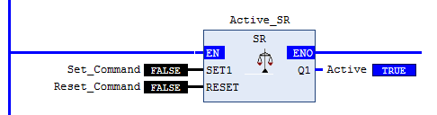
This effectively packages up the same logic used in previous example, but places it in a reusable Function Block
Non Setting Latch
Personally, I dislike Set Coils or Set/Reset blocks.
I would achieve the same result this way:
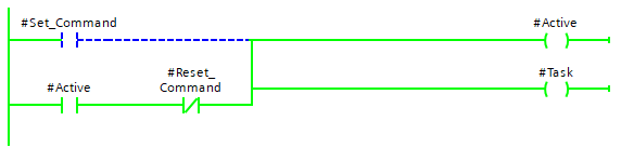
The above approach is much easier to visually see why the Task variable is still active. This becomes especially useful in fault finding where Latch systems can become very confusing with many Set Coils.
Interlock Logic
The best thing about Ladder is that it is highly visual, it’s very easy to see what’s happening. This makes it great for large interlock management:
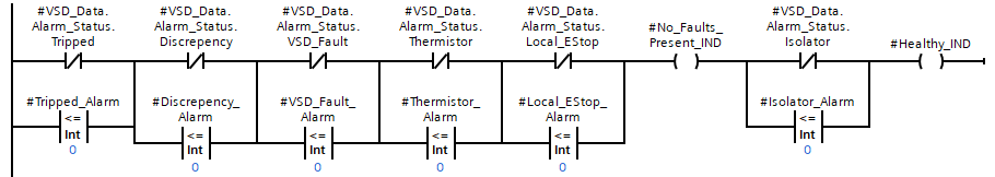
Healthy_IND is set to TRUEIf any of the pathways in the above logic are broken, then the Healthy_IND variable will be FALSE.
The logic consists of many checks against Alarm Statuses, with a Branch around to provide continuation of TRUE logic if the alarm is disabled (set to 0 in this case).
Notice that there is an Inline Coil with No_Faults_Present_IND attached to it. Inline Coils are not available in all development environments, but most permit an Open Branch with a Coil placed on it instead.
Math
Ladder is not strong when it comes to complex mathematics, especially if multiple stages to an equation are required. Consider the following:

Achieving this with standard Ladder elements would look something like this:
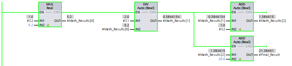
Although the result is correct, it’s hard to follow and requires many “Placeholder” variables (Math_Results)
Most development platforms allow for some variation of an Expression input. In CODESYS for example, you can use the Execute instruction to place Structured Text inside the Ladder language:
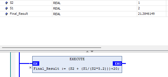
The Final_Result variable shows the correct value, without the messiness of the Ladder approach.
TIA Portal allows SCL (Structured Text) to be used in Ladder with a special SCL Network. Alternatively, the not-so-nice-to-use Calculate instruction can be used:

Network Management
Personally, I like to use Networks (or Rungs in Allen Bradley) to containerize logic into sections that perform a common method. For example:

The above shows the “Management Of Channel_Fault Alarm”. This Network, although containing more than 1 instruction, works as a single method… To manage the Channel Fault Alarm.
We can see that when the OOR_Fault is TRUE, a TON (On Delay Timer) is started. When that completes, two Coils are set to TRUE and the Condition input for the Global_Alarm_Manager is set to TRUE.
This then manages the alarm according to the Function’s logic and outputs to the Channel_Fault variable.
Some may argue that the TON and preceding logic should have been on a separate Network, then the Global Alarm Manager should have followed after. However, my counter to that is that it becomes more difficult to realize the relationship between the two rungs. The approach above means the end result is visual and easy to follow, it’s clear to see how Channel_Fault is set and why.
This can get trickier with large Networks, so consider consolidating into Functions or Function Blocks where appropriate!
Conclusion
Ladder is a great language and learning it means that you’ll be capable of programming nearly all requirements that are set out in front of you.
With Ladder being the most used language in PLC design, you’ll be able to follow most programs written by other programmers too.
Remember that Ladder was originally designed for maintenance and electrical disciplines to read easily, offline, printed out. Ladder was never designed to be a “Complex” language.
By taking advantage of the Networks and “Ladder-like” approach to the language, flow and logic containment is easy. Keeping your logic easy to read and manageable comes naturally to Ladder.
Remember to comment variables and networks and you can’t really go wrong!